Homemade Noises Part 1: Making Things Louder
Published:
Messing around with guitar pedals and finding fun sound combinations is a blast and often a needed distraction from practicing. Pedals, however, are expensive at $100-300 a pop, which makes it rather difficult to own enough to play around with (or any at all in my case). Guitar stores will let you try some, but it is cumbersome to set up a chain in a store and they will eventually kick you out.
Thus, I took the deep plunge into figuring out how they work, so I could build some of my own. Luckily, there are some pretty great forums on the internet about guitar pedals where I could learn all about them. And Wikipedia has an abundance of information on circuits and provides plenty of little theory rabbit holes.
I have a little bit of experience with building circuits, but significantly less with designing them, so I began with a simple boost pedal. A boost pedal “boosts” the signal by adjusting the gain. This is useful for dynamics when playing. Some boost pedals will have several other features built-in, such as an equalizer, but for simplicity I stuck with a single parameter boost.
Circuit
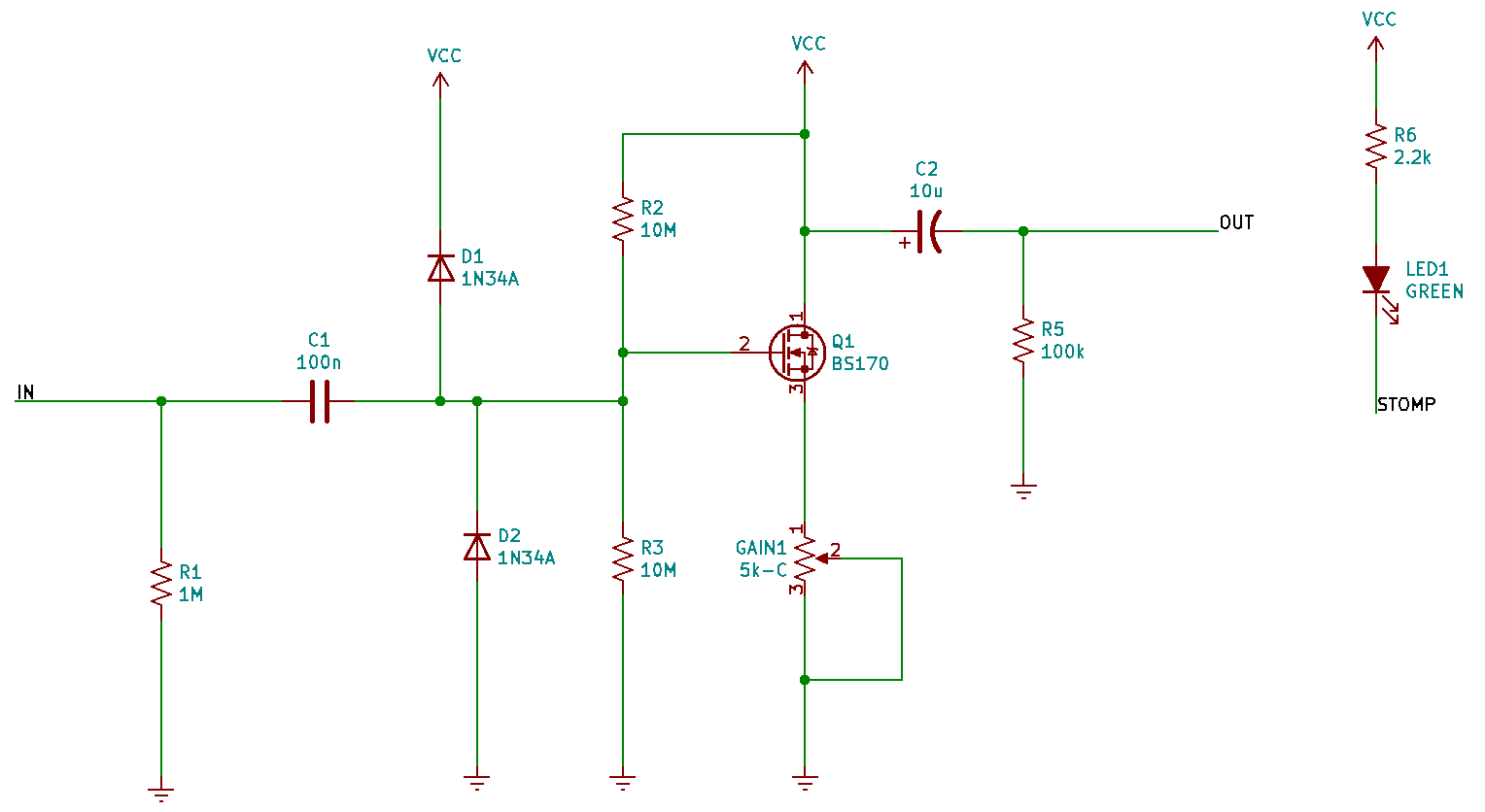
The circuit is based on this Tayda booster. I replaced the 1N4148 diodes with 1N34A germanium diodes and used a red LED (lower voltage drop). The germanium diodes clip at about half the voltage giving more fuzz to the sound. Using the 1N4148’s would give a cleaner tone.
The above circuit is an example of an N-channel MOSFET common-source amplifier.That is a mouthful, so I will try to break it down.
The most important component in this circuit is Q1, a transistor. It is a BS170 transistor (same, but higher rated than the popular 2N7000), which is a special type of transistor called an N-channel MOSFET. Transistors do not have to just be used for switching. They can also be utilized to amplify signals via biasing. This is great because that is exactly what a booster pedal should do: amplify the signal.
One way to amplify signals with FET (JFET or MOSFET) transistors are common-source circuits. These have the gate (2) and drain (1) both tied to power and the source (3) to ground (or vice versa). These pages [1, 2] provide in-depth explanation as to how these circuits work.

To get maximum voltage gain out of the drain (1) we need to bias the input to the gate (2). There are several biasing techniques, which use resistors and two DC sources to bias. However, you can also forward bias a transistor with zener diodes. This is helpful since the diodes are independent of the supply voltage. I end up using germanium diodes, which are the same, but start to forward bias at a much lower initial voltage.
I should note that op-amps are a popular component used for amplification. They amplify signals well, are small, and are now very cheap (~$0.25 each). But op-amps themselves are just small integrated circuits with cascaded transistor amplifiers inside. For larger pedals with boosting stages it makes sense to use simple op-amps instead of separate transistor circuits, however, for a single booster pedal it feels like cheating.
The transistor-based amplifier is the meat of the circuit and how it “boosts” the guitar signal. There is also a status LED light, and connections to the potentiometer knob, stomp switch, input/output jacks, and power jack.
Assembly
The circuit is fairly simple and based on a previous successful design, so I did not mess around with breadboarding and directly ordered a PCB. D1 and D2, the diodes, are the only components I would want to mess around with as they will control the amount of distortion. I did not, but you could put pin headers on the PCB so it is easier to swap out diodes and try different ones.
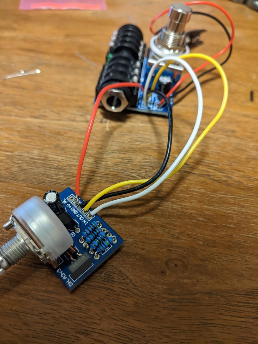
With the PCB in hand it is just a matter of soldering everything together. Due to its size this board does not take very long to assemble.
Decoration
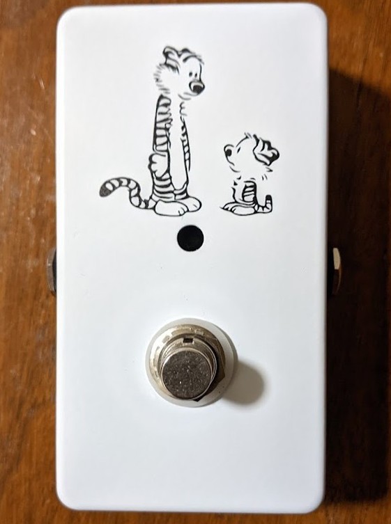
Every pedal hoarder should know that the aesthetics are paramount to good sound. Not really, but I am much more likely to put a pedal on display if it looks good and I am then, in turn, more likely to use it if I see it frequently.
After some practice I finally nailed the C&H design.
Sound Test
With the aesthetics out of the way we can finally plug it in and see what it sounds like.
Summary and Improvements
The pedal sounds great for a clean booster, it only cost ~$20, and assembly took about an hour. Sourcing parts and ordering them took a while, but now that I have bulk sets of components I will not need to go through as much sourcing next time.
Simple boosting circuits are a good segue into bigger overdrive/distortion/fuzz circuits. They operate off of the same concept of diode + amplifier. Usually op-amps are used in place of transistor circuits. Additionally, cascoded amplifier circuits are utilized which use several amplifier circuits together with various diode biasing to achieve more distortion effects.